Module TPS - 3491
Analog - Digital Signal Conversion Training System
Technical Characteristics
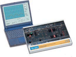
The trainer is enclosed in a metal case with a wide experiment platform printed circuit board (22cm x 35 cm). This ensures easy handling and good visibility of the components.
The components are located on the board, which has a silkscreen print of the analytical circuit and component symbols. The central part
of the experiment board includes all the circuit block drawings and all
the hands on components and test points.
The protected components are located on the circuit board, clearly visible to the student and protected by a sturdy transparent cover.
The system includes a built in power supply with +12V, +5V, and variable DC voltage outlets. An included low voltage external AC power adapter feeds the system.
The system includes:
• Power supply
• 8 bit ADC
• 8 LEDs
• 8 bit DAC
• 8 switches
• Signal multiplexer
• Signal demultiplexer
• Parallel to serial converter
• Serial to parallel converter
• Data encoder
• Data decoder
• 8K x 8 RAM for signal storage and reconstructing
• Pulse generator, counter, and control circuit
• Preamplifier and microphone
• Audio amplifier and speaker
• SES Lab unit with two-channel scope and function generator, which
communicates with a PC to control the function generator and oscilloscope
display, including spectrum analysis
• PC Software (Optional)
The system can be integrated with the other communication trainers in order to simulate advance experiments.
The system includes extension connector for future technology add-ons.
This course introduces the student to analog and digital signal conversion. The course provides comprehensive hands-on experiments including data acquisition, analog to digital conversion, digital to analog conversion, data storage, signal sampling, storage and reconstruction, voice storage and regeneration, conversion accuracy, sample and hold, CODEC coding/ decoding, compressor, expander, PAM, PCM, DPCM, DM data modulation, parallel to serial, serial to parallel.
Description
The system is stand-alone containing all the necessary electronic components needed for performing the experiments. The experiment area is in the central part of the trainer including circuit drawing, test points, and peripheral outputs and inputs. The circuit board contains visible component circuits protected by a sturdy transparent cover.
The system includes a built in power supply with +12V, +5V, and variable DC voltage.
The system includes the SES Lab unit with a two-channel oscilloscope and a function generator, which communicates with a PC to control the function generator and oscilloscope display, including spectrum analysis.
The built-in function generator can be operated manually, controlled
by the embedded micro-controller for sine/triangle, sweep/constant signals.
Experiments
This system enables the student to perform several experiments and covers the following topics:
• Analog to Digital Conversion – ADC• Digital to Analog Conversion – DAC
• ADC - DAC compatibility
• DAC - ADC compatibility
• RAM writing and reading
• Signal sampling and storing in a RAM
• Signal reconstruction
• Conversion accuracy
• Voice storage and regeneration
• PAM modulation and demodulation
• RAM TDM transmission and reception
• PCM signal modulation and demodulation
• DPCM signal modulation and demodulation
• DM signal modulation and demodulation
• Codec coding – decoding
• Parallel to serial
• Serial to parallel