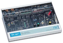
Module TPS - 3071
PLC Control Training System
Technical Characteristics
The trainer is enclosed in a metal case, which has a wide experiment printed circuit board (22 cm x 34 cm). This ensures easy handling and good visibility of the components.
The components are located on the board, which has a silkscreen print of the analytical circuit and component drawings. The central part of the experiment board includes all the circuit block drawings and the all the hands-on components, test points, and banana sockets.
The fixed components are located on the top side of the panel under a sturdy transparent cover.
The system includes a built-in power supply with +12V, +5V, and variable DC voltage outlets. An included external low AC voltage power adapter feeds the system.
The system includes
• Stepper motor with two pointers
• Stepper motor driver
• Limit switch
• Hall effect sensor
• Optocoupler sensor
• DC motor control
• Dynamo
• 555 timer, for PWM control
• Elevator simulator
• Traffic light simulator
System Controllers
The system can be controlled as follows:
• PLCs’ ladder diagram software (included)
• PLC (not included)
• APPLIC-12 or APPLIC-18 (not included)
PLCs – Ladder Diagram Application Software
This program enables the user to build ladder diagram programs using the
following elements:
• Switch input
• Complementary switch input
• Outputs
• Coils
• Timers
• Counters
• One shots
• Drums
• ADC
• DAC
The software can be used as a simulator and can turn the PC into a PLC for the TPS-3071 PLC Control Trainer.
This course introduces the student to control application using software control, PLC or microcontroller. The student control sensors and motors performing exercises like traffic light control, elevators control and consumers Application. The course develops basic and advance skills application control.
Description
The system is stand-alone, containing all the necessary electronics components needed for performing the experiments. The experiment area is in the central part of the trainer including circuit drawing, test points, and peripheral outputs and inputs.
The circuit board includes visible component circuits protected by a sturdy transparent cover.
The system contains traffic light, elevator, motor and dynamo, stepper
motor limit switches, optocoupler, Hall effect sensor, temperature, and
light control. Control of the application is available through three options:
Ladder diagram software, industrial PLC, or microcontroller.
Experiments
This system enables the student to perform experiments and application
as follows:
• Basic in control
• Basic ladder diagram application
• Traffic light control
• Elevator control
• Temperature
• Light control
• Stepper motor control
• DC motor control
• Speed control
• Hall effect sensor
![]() A teacher
guide, a student experiment manual accompany the
system
A teacher
guide, a student experiment manual accompany the
system